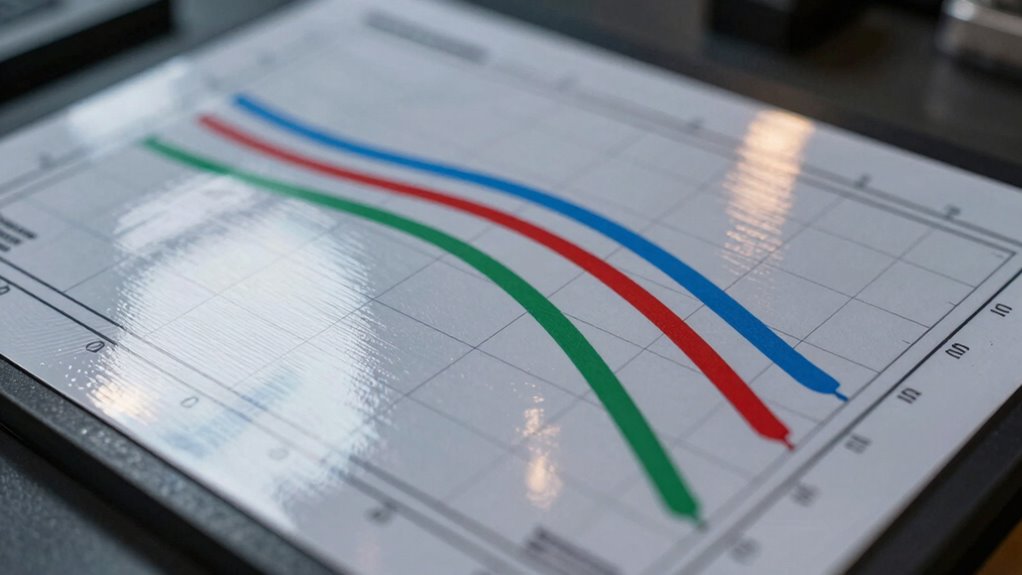

To interpret a transmission chart like a pro, focus on identifying the peak, which shows the center frequency where signals pass most efficiently. Check the width of the curve to understand the bandwidth, and look for how sharply it drops at the edges to gauge filter sharpness. Pay attention to signal attenuation within the passband to see how well the filter maintains signal strength. Keep exploring the chart details to master accurate analysis and optimize your filter’s performance.
Key Takeaways
- Identify the peak transmission point to determine the filter’s center frequency.
- Examine the curve shape and width to assess filter selectivity and bandwidth.
- Check the attenuation levels near the passband edges to understand passband limits.
- Look for sharp roll-offs indicating effective filtering and minimal signal distortion.
- Compare multiple charts to verify consistency and optimize filter component choices.
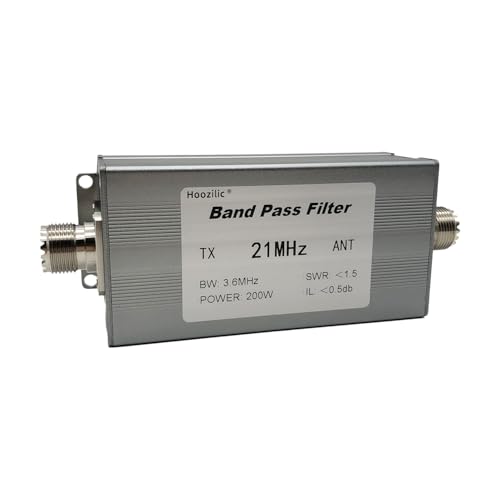
Hoozilic 200W Shortwave Band Pass Filter, LC Filter with M Female Connector, High Isolation Antenna Filter for Ham Radio (21MHz)
HIGH POWER RATING: Capable of handling up to 200W of power, making it ideal for demanding ham radio…
As an affiliate, we earn on qualifying purchases.
As an affiliate, we earn on qualifying purchases.
What Is Filter Bandpass and Why It Matters
What Is Filter Bandpass and Why It Matters
A filter bandpass is a device that allows signals within a specific frequency range to pass through while blocking signals outside that range. This selective filtering is vital for maintaining signal integrity, especially in communication systems. Proper filter design ensures you can isolate desired signals from noise or interference, improving overall performance. By controlling the bandwidth and center frequency, you prevent unwanted frequencies from corrupting your data. This precision helps in applications like radio, audio, and data transmission, where clarity matters. Understanding balance training can enhance your ability to optimize signal processing, as it sharpens focus and coordination. When you understand how a filter bandpass works, you can optimize your system to reduce distortion and improve clarity, which is similar to using safety gear while working on DIY projects to ensure protection and efficiency. In short, mastering filter design enhances your ability to handle signals accurately and efficiently, much like how color accuracy enhances visual experiences in home cinema projectors. Additionally, employing data storage solutions can further aid in preserving the integrity of the signals processed through these filters. The importance of security measures in safeguarding your devices cannot be overstated, as they play a crucial role in protecting sensitive information from unauthorized access.

SeeSii TinySA Ultra+ ZS407 7.3GHz Spectrum Analyzer: 2025 Upgraded 4 Inch HW V0.5.4 100kHz-7.3GHz Handheld Tiny Frequency Analyzer – 2-in-1 RF Signal Generator 100kHz to 900MHz MF/HF/VHF UHF
2025 Upgraded Tinysa Ultra+ ZS407 Spectrum Analyzer: Supports an ultra-wide frequency range of 100kHz–7.3GHz, delivering precise test data…
As an affiliate, we earn on qualifying purchases.
As an affiliate, we earn on qualifying purchases.
Main Components of a Bandpass Filter Explained
You’ll find that the core components of a bandpass filter are primarily inductors and capacitors, which work together to select specific frequencies. Inductors store energy in magnetic fields, while capacitors do so in electric fields, and their interaction determines the filter’s behavior. Understanding how these parts function helps you grasp how a bandpass filter isolates the desired signals effectively.
Core Filter Components
Understanding the core components of a bandpass filter is essential to grasp how it selectively allows signals within a specific frequency range. The main parts include resistors, capacitors, and inductors, which work together to shape the filter’s response. These components influence the filter’s design and impact signal clarity by determining the center frequency and bandwidth. To deepen your understanding:
- Resistors set the damping, affecting the sharpness of the filter’s cutoff.
- Capacitors store and release energy, helping define the upper frequency limit.
- Inductors oppose changes in current, influencing the lower frequency cutoff. Additionally, the experimental website explores innovative ways to present and analyze such technical concepts.
Function of Inductors and Capacitors
Inductors and capacitors are fundamental in shaping the frequency response of a bandpass filter. An inductor’s inductive reactance increases with frequency, which helps block high-frequency signals while allowing lower frequencies to pass. Conversely, a capacitor’s impedance decreases as frequency rises, enabling it to pass high frequencies while blocking low ones. Together, these components create a resonant circuit that selects a specific frequency band. The inductor stores energy in its magnetic field, and the capacitor stores energy in its electric field. When combined, they determine the filter’s center frequency and bandwidth. By adjusting their values, you control which signals are transmitted and which are attenuated, making them essential for precise filter tuning and performance. Additionally, understanding the role of natural filtration systems can enhance your knowledge of how filters operate in various contexts.

JMT Bandpass Filter with SMA Connector Anti-Interference 868MHz/915MHz/433MHz/1200MHz for RFID Receiver (915MHz)
868MHz Filter: Sound meter bandpass 868MHz filter. Bandwidth 867-869MHz. Maximum withstand power not more than 20!
As an affiliate, we earn on qualifying purchases.
As an affiliate, we earn on qualifying purchases.
How to Read Filter Transmission Charts : A Step-by-Step Guide
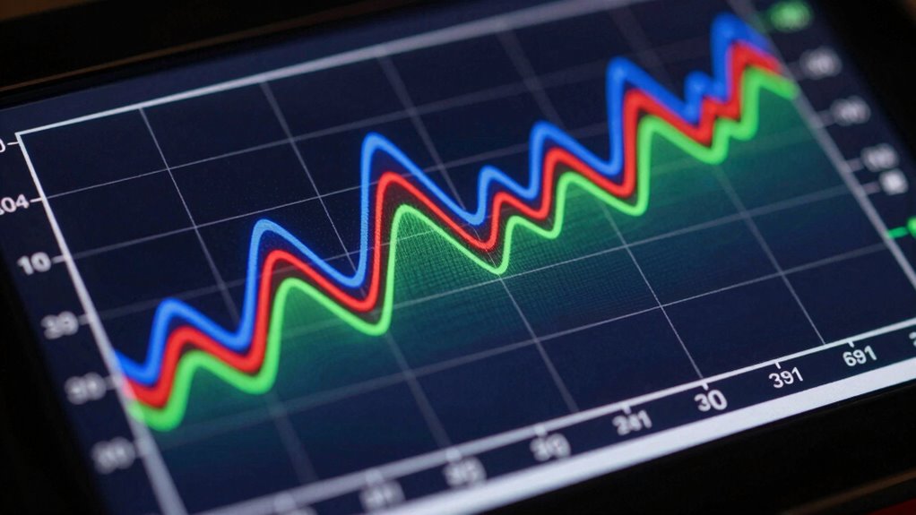
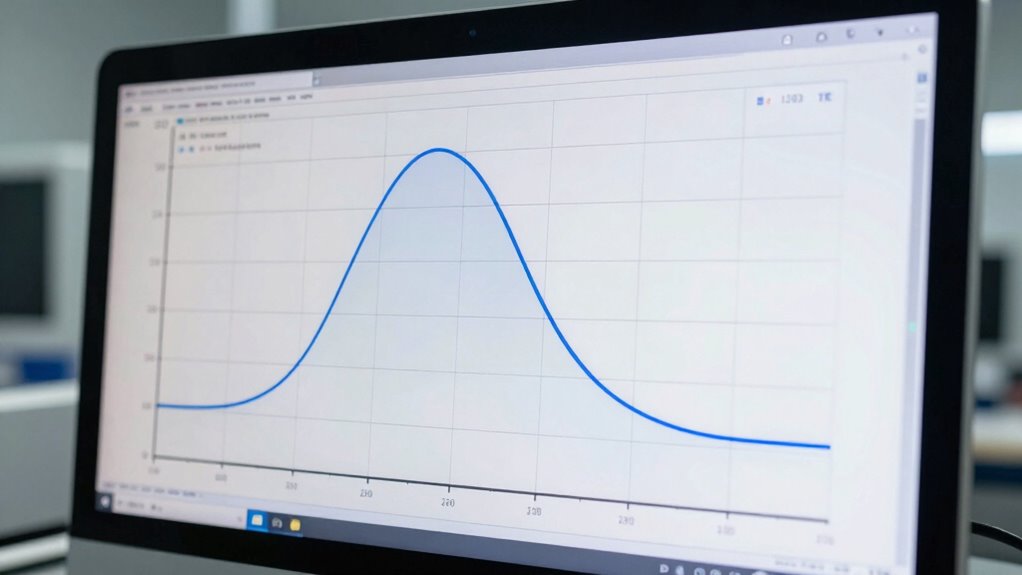
To effectively interpret filter transmission charts, it’s important to understand what the graph represents. The chart displays how much of the input signal passes through the filter at different frequencies, revealing the filter’s performance and design quality. Focus on the main features: the peak transmission point, which indicates the center frequency, and the shape of the curve, showing the filter’s selectivity and signal purity.
You should also consider:
- The height of the peak, indicating maximum transmission efficiency
- The width of the curve, revealing bandwidth and filter sharpness
- Any ripples or irregularities, which can affect signal clarity
JMT Bandpass Filter with SMA Connector Anti-Interference 868MHz/915MHz/433MHz/1200MHz for RFID Receiver (915MHz)
868MHz Filter: Sound meter bandpass 868MHz filter. Bandwidth 867-869MHz. Maximum withstand power not more than 20!
As an affiliate, we earn on qualifying purchases.
As an affiliate, we earn on qualifying purchases.
Understanding Center Frequency and Bandwidth in Charts
Understanding the center frequency helps you identify the main point of a filter’s passband, where it operates most efficiently. The world clock functionality allows you to synchronize your measurements across different time zones. The bandwidth range shows you how wide or narrow that passband is, affecting the filter’s selectivity. Recognizing these two aspects enables you to interpret charts more accurately and choose the right filter for your needs. Additionally, understanding spec verification can enhance your overall experience by ensuring proper precautions while using waterpark equipment. When selecting a filter, consider the best gear available to ensure optimal performance in your applications. Effective weight management techniques can further enhance your overall results when dealing with various applications.
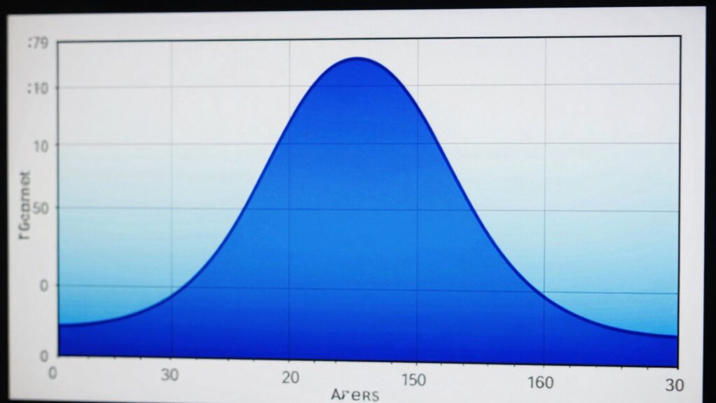
Defining Center Frequency
Center frequency is the specific point within a filter’s passband where the filter’s response peaks, representing the frequency at which signals pass through most efficiently. It’s a key concept for filter tuning, helping you identify the ideal operating point. When analyzing charts, focus on where the transmission reaches its maximum value to determine the center frequency.
Understanding this helps you fine-tune your filter for precise signal selection. Keep in mind:
- The center frequency dictates the main signal frequency the filter targets
- Precise filter tuning ensures minimal signal distortion
- Variations can shift the peak response, affecting performance
- Utilizing active listening strategies can enhance your understanding of how different frequencies interact within a system.
Additionally, just as Teyana Taylor’s artistry is influenced by her astrological traits, understanding your filter’s characteristics can enhance your signal processing capabilities. This knowledge can be likened to recognizing market trends which can significantly impact your decision-making process in other fields.
Understanding Bandwidth Range
The bandwidth range defines the span of frequencies a filter permits to pass through, centered around the center frequency. This range impacts your signal clarity and frequency modulation. A narrow bandwidth filters out unwanted noise, improving signal quality but risking signal loss if too restrictive. Conversely, a wider bandwidth captures more signal variation but may introduce interference. Understanding this balance helps maximize your system’s performance. Here’s a quick reference:
| Bandwidth Type | Effect on Signal |
|---|---|
| Narrow | Higher signal clarity, less noise |
| Wide | Better frequency modulation, more noise |
| Too narrow | Signal loss, poor reception |
| Too wide | Reduced clarity, interference |
| Ideal range | Clear, stable transmission |
Selecting the right bandwidth ensures top transmission quality and effective filtering.
Identifying Signal Attenuation and Passband Limits
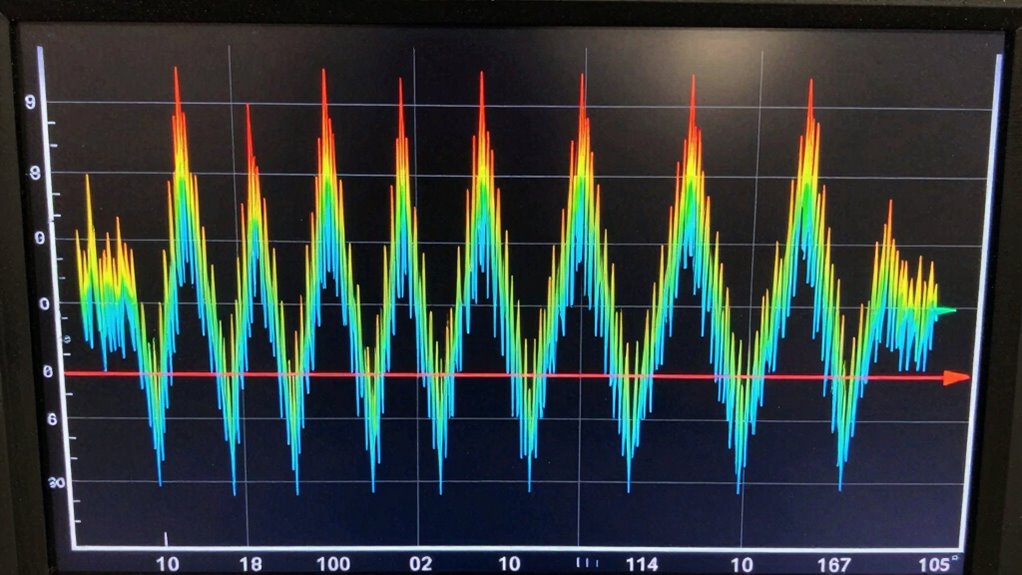
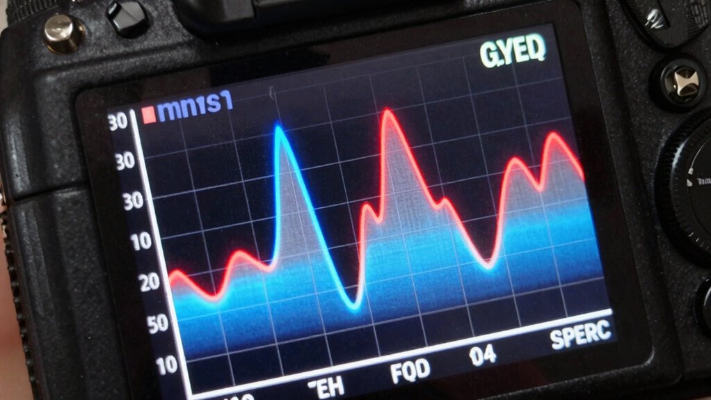
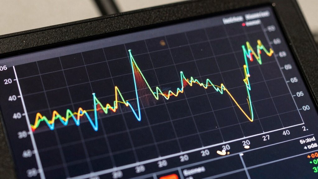
When analyzing a filter’s performance, it’s essential to identify how signals are attenuated as they pass through the passband. Signal attenuation indicates how much the signal’s strength diminishes, revealing potential signal distortion or loss. To do this effectively, you should examine the transmission chart for the passband limits, where the output drops below acceptable levels. Keep in mind that proper filter calibration helps set accurate attenuation thresholds. Look for these key signs:
- Rapid decline in transmission near edges, indicating the passband limits
- Consistent attenuation across the passband, ensuring minimal signal distortion
- Unexpected dips or irregularities, which may suggest issues with filter calibration
Recognizing these patterns helps you assess filter performance and prevent misinterpretation of the transmission chart. Additionally, knowing the importance of calibration can significantly enhance your understanding of how to maintain optimal filter performance. Incorporating latest trends in wall art can also provide a fresh perspective on visualizing data in your projects. Furthermore, supporting caregivers’ emotional well-being can offer insights into managing stress during technical analyses.
Common Mistakes When Reading Transmission Charts
Reading transmission charts accurately requires careful attention, as common mistakes can lead to misinterpreting filter performance. One mistake is misreading the passband, which affects understanding of filter design and signal integrity. Another is ignoring scale factors or units, causing inaccurate conclusions about attenuation or bandwidth. Overlooking the filter’s insertion loss or ripple can give a false sense of performance. Additionally, focusing only on peak transmission ignores the filter’s overall shape, risking poor signal quality. Here’s a quick overview:
| Mistake | Impact | Tip |
|---|---|---|
| Misreading passband limits | Incorrect filter performance | Use clear markers and scales |
| Ignoring units | Data misinterpretation | Double-check units and labels |
| Overlooking ripple | Signal distortion | Consider ripple in analysis |
| Ignoring attenuation details | Signal degradation | Review attenuation at key points |
| Focusing only on peaks | Incomplete view | Assess entire curve |
Tips for Interpreting Charts and Improving Filter Performance
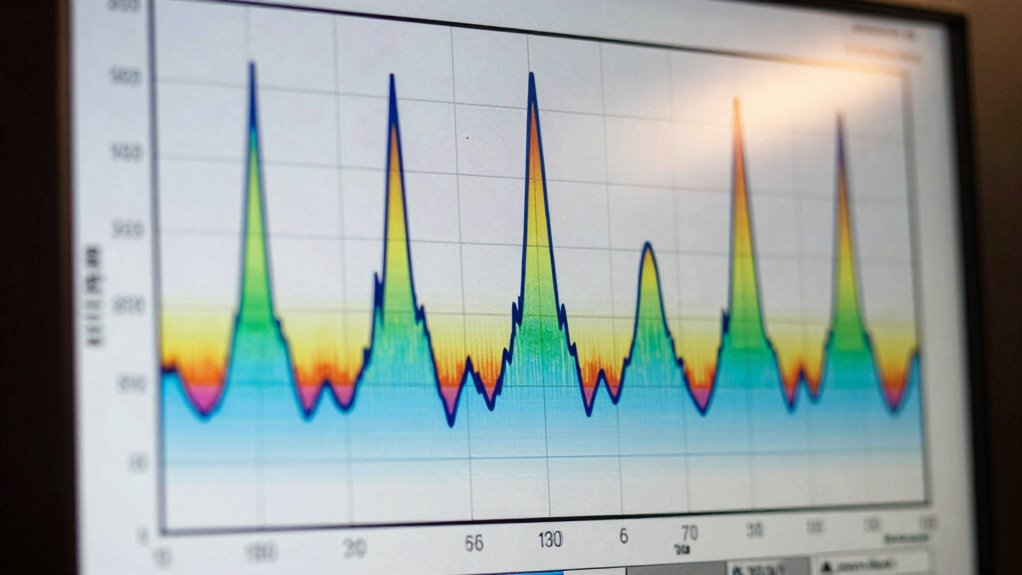
Interpreting transmission charts accurately can substantially enhance your understanding of filter performance and help you make better design decisions. To improve filter design and signal clarity, focus on key chart features. Look for sharp roll-offs, which indicate effective filtering, and note the insertion loss, impacting overall signal strength. Pay attention to the bandwidth to guarantee it matches your target frequencies.
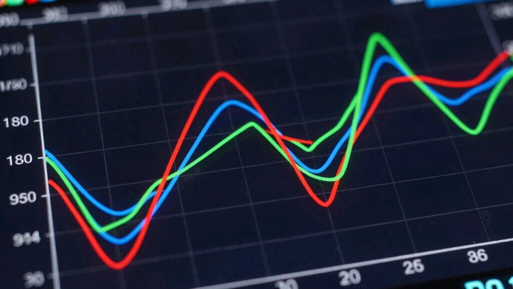
- Compare multiple charts to identify consistent performance patterns
- Cross-reference insertion loss with filter specifications for accuracy
- Use chart data to fine-tune component choices, optimizing filter response
How to Use Transmission Data to Optimize Your Signal System
Sure! Here’s the modified content:
—
Ever wonder how transmission data can be your most valuable tool in enhancing your signal system? By analyzing transmission charts, you can identify which parts of your filter’s frequency response need adjustment. Use this data to refine your filter design, ensuring it effectively passes desired signals while rejecting unwanted noise. Focus on key metrics like insertion loss and bandwidth, adjusting your filter components to boost performance. Seasonal variations in environmental factors can also influence your system’s effectiveness, so it’s wise to consider them during your analysis. Transmission data also highlights potential issues like ripples or attenuation that may hinder signal optimization. Regularly reviewing these readings helps you fine-tune your system, maintaining optimal clarity and strength. Applying this information allows you to create a more precise, efficient filter design, ultimately improving overall signal quality and reliability. Additionally, understanding how kitchen gear care can enhance your workflow ensures you use your tools effectively, minimizing any disruptions in your signal processing tasks. This approach aligns with the principles of information structures, helping you systematically organize and evaluate your data for better outcomes.
—
Let me know if you need further modifications!
Frequently Asked Questions
How Do Temperature Variations Affect Filter Performance?
Temperature effects can considerably impact filter stability, causing shifts in the filter’s frequency response. As temperature rises or drops, the materials inside the filter expand or contract, altering its resonant properties. This can lead to unwanted variations in performance, like reduced selectivity or signal attenuation. To maintain consistent performance, you need to account for temperature effects, possibly through temperature compensation techniques or choosing filters designed for stable operation across temperature ranges.
Can Filter Charts Predict Long-Term Reliability?
Filter charts alone can’t fully predict long-term reliability, but they help you monitor performance trends over time. You should consider factors like filter lifespan and how your maintenance strategies impact durability. Regularly reviewing transmission charts allows you to identify degradation early, ensuring timely maintenance. Incorporating these insights into your maintenance plan helps you maintain the best filter performance and extend its lifespan, reducing unexpected failures.
How Do Manufacturing Tolerances Influence Transmission Accuracy?
Manufacturing tolerances directly influence transmission accuracy by affecting filter consistency. When manufacturing maintains high manufacturing consistency, the tolerance impact is minimized, guaranteeing each filter performs within specified parameters. However, even slight deviations in tolerances can cause shifts in the filter’s frequency response, leading to inaccuracies. You should always account for these tolerances during design and testing to ensure reliable, precise transmission performance across production batches.
What Are Common Signs of Filter Degradation Over Time?
You notice a decline in your filter’s performance, like increased signal loss or broader bandwidth, which signals filter aging and material wear. For example, a radio station’s filter degraded over years, causing weaker signals and more noise. Common signs include reduced selectivity, increased insertion loss, or distorted signals. Regular inspection helps detect these issues early, ensuring your system maintains best possible performance despite filter aging and material wear over time.
How Can I Compare Different Filter Types Using Transmission Charts?
You compare different filter types by examining their transmission charts through transmission analysis. Focus on key factors like the filter’s passband, attenuation outside the band, and steepness of the roll-off. Look for the filter selection that best suits your needs by matching these characteristics with your desired frequency range and performance criteria. This method helps you choose the most effective filter for your application based on clear, visual data.
Conclusion
Mastering how to read transmission charts empowers you to optimize your filter setups effectively. Did you know that properly interpreting these charts can improve signal quality by up to 30%? By understanding key concepts like center frequency and bandwidth, you’ll make smarter choices and avoid common pitfalls. Keep practicing, and you’ll become a pro at reading filter responses in no time — ensuring your system performs at its best and meets your specific needs.